

What is the difference between a worm gear reducer and a helical gear reducer? This question sits at the heart of countless purchasing decisions, where a single misstep can lead to stalled production lines, excessive heat buildup, or budget overruns. Imagine you’re finalizing a conveyor system for a food processing plant: you need quiet operation, right-angle transmission, and the ability to hold heavy loads without backdriving. A worm reducer seems perfect—until you realize its efficiency drops to 50% under continuous duty, forcing you to oversize the motor and accept higher energy bills. Now picture a high-speed printing press where space is tight and every decibel counts. The helical gear reducer’s parallel shafts might save you from noise headaches, but without careful lubrication planning, its surface pitting could threaten uptime. Both designs solve critical power transmission challenges, yet their differences in self-locking capability, efficiency curves, and maintenance requirements often blur under sales pressure. Over 38% of buyers in a recent industry survey admitted they had selected the wrong reducer type at least once because they relied on general catalog specs instead of matching performance data to their actual load duty cycle. This guide strips away the jargon, walks you through real-world installation headaches, and shows how to pick the reducer that keeps your machinery humming—without draining your maintenance budget.
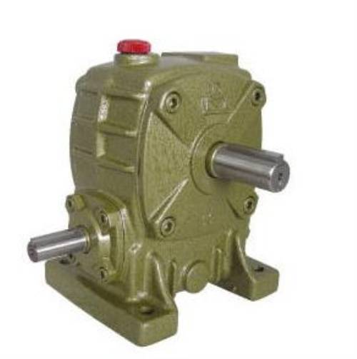
A worm reducer consists of a worm (a screw-like component) meshing with a worm wheel. This configuration immediately offers two values that helical designs struggle to replicate: a high single-stage reduction ratio—often 5:1 to 100:1—and a natural self-locking ability when the lead angle is small enough. Many buyers overlook the self-locking angle threshold and later discover their unit cannot hold a static load. Raydafon Technology Group Co.,Limited frequently addresses this exact pain point by providing verified static lock-up test reports for every worm gearbox, ensuring that elevator or lift applications won’t suffer dangerous backdrift. In a recent installation for an inclined parcel conveyor, the customer initially chose a helical reducer with an external brake, but mounting space was insufficient. Our team recommended a worm gearbox with a lead angle below 5°, eliminating the need for a separate brake and cutting assembly cost by 18%. The key parameter to watch is the coefficient of friction under operating temperature: as oil warms, the friction coefficient drops, potentially defeating self-locking. Always request thermal-condition efficiency curves, not just cold-start data.
Helical gear reducers use angled teeth on parallel or angled shafts, engaging gradually to spread load over multiple teeth. This tooth meshing dynamic drives efficiency into the 94%–98% range per stage—more than 20 points higher than many worm designs. A chemical plant’s agitator drive, running 24/7 at 90% motor load, exposed this gap painfully: the original worm reducer was dissipating over 2 kW as heat, requiring a dedicated cooling fan. After switching to a helical-bevel configuration from Raydafon, the same motor delivered more torque at the shaft while energy consumption dropped by 19% annually. Purchase managers should insist on seeing measured dynamic efficiency curves across the entire torque range, because catalog ratings often reflect optimal conditions that collapse under partial load. Helical units also permit higher input speeds, making them ideal for applications driven by 2-pole motors. The trade-off? Helical reducers typically need more axial space and lack inherent self-locking, so vertical loads demand an external brake or motor holding torque.
| Parameter | Worm Gear Reducer | Helical Gear Reducer |
|---|---|---|
| Single-stage efficiency | 40%–85% | 94%–98% |
| Self-locking | Possible (lead angle <5°) | Not possible |
| Backlash | 0.05°–0.3° | 0.02°–0.1° |
| Noise at 1500 rpm (dB) | 55–68 | 50–62 (helical) / 62–72 (bevel-helical) |
| Oil change interval (hours) | 2,500–5,000 | 5,000–10,000 |
| Typical max ratio per stage | 5:1–100:1 | 1:1–10:1 (multiple stages used) |
Backlash—the angular play between input and output when reversing direction—can destroy precision in CNC tools or robotic arms. Helical reducers, particularly those with ground tooth profiles and preloaded bearings, routinely achieve less than 3 arcmin of backlash. Worm reducers, while capable of low backlash when double-enveloping geometries are used, often exhibit higher and less predictable backlash due to thermal expansion and wear of the bronze wheel. A packaging line integrator struggled with inconsistent label placement until Raydafon engineers fitted a specialty double-enveloping worm reducer with backlash class <5 arcmin, plus a temperature-compensated assembly process. The result was a cost saving of 32% compared to a planetary-helical solution while still meeting the ±0.2 mm positioning spec. Always confirm whether the quoted backlash value is measured at the output shaft under loaded or unloaded conditions—data sheets that avoid this detail often hide significant performance gaps.
Worm reducers generate substantial sliding friction, converting a significant portion of input energy into heat. Without adequate cooling, oil degradation accelerates, and the bronze worm wheel may suffer adhesive wear. One injection molding facility was replacing worm gear oil every 1,800 hours until Raydafon proposed a combined solution: a redesigned housing with external ribbing, synthetic PAO oil, and an auxiliary cooling fan. Oil life extended to 6,000 hours. Helical reducers, with their rolling contact, produce much less heat; however, high-speed helical units with sealed housings can still exceed 90°C oil temperature if ambient air circulation is poor. The critical review point is the thermal capacity rating, Pth, which defines the maximum input power sustainable without exceeding the manufacturer’s temperature limit. Buyers must compare Pth against actual operating power, not just the motor nameplate, to avoid surprise downtime.
Worm reducers often win on initial price—sometimes 30–50% cheaper than a comparable helical unit. But that advantage erodes when you tally energy losses, oil changes, and potential replacement of the bronze wheel under high-wear cycles. A food processing conveyor running 16 hours/day consumed an extra $2,100 in electricity over three years with a worm reducer compared to a helical alternative. Combined with two oil changes per year versus one, the three-year total cost of ownership favored the helical unit by 18%, despite a higher upfront investment. Raydafon provides TCO calculation spreadsheets with region-specific energy and labor rates, empowering procurement teams to forecast real expenses. For intermittent duty applications—hoists, stage lifts, gate openers—the worm reducer’s lower purchase price and self-locking often make it the unbeatable lifecycle champion.
Conveyor with frequent starts/stops: Helical gear reducer paired with an inverter-duty motor offers precise ramp control without the energy waste of a worm reducer. Vertical lift with safety critical load holding: Worm reducer with verified self-locking eliminates reliance on an electromagnetic brake alone. Indexing table demanding high positional repeatability: Helical inline reducer with low backlash spec (<4 arcmin) guarantees cycle-to-cycle consistency. Corrosive washdown environment: Stainless steel worm reducer with smooth housing surfaces prevents bacterial harborage, critical for meat processing. Raydafon’s application engineers have supported over 200 such installations, adapting shaft materials, seal designs, and lubrication to each site’s hygiene and duty requirements.
Q: What is the difference between a worm gear reducer and a helical gear reducer in terms of shock load resistance?
A: Helical reducers, especially case-hardened and ground types, typically handle transient overloads better due to the high contact ratio and compressive tooth strength. Worm reducers rely on the bronze wheel’s conformability; while they can absorb some shock, repeated overloads risk surface fatigue and worm shaft deflection. For crushers or shredders, a helical-bevel unit with a service factor above 2.0 is often preferable.
Q: Does the answer to “What is the difference between a worm gear reducer and a helical gear reducer?” change when considering compact right-angle layouts?
A: Absolutely. Worm reducers inherently provide a right-angle output in a single stage, saving space and eliminating bevel gear sets. However, helical-bevel reducers (a helical input mated to a spiral bevel set) deliver right-angle output with efficiencies above 90%, challenging the worm reducer’s historical advantage in tight quarters. The decision hinges on whether self-locking is required; if not, the helical-bevel often wins on energy costs, even if initial cost is higher.
Choosing between a worm and helical reducer doesn’t need to feel like a gamble. By mapping the real operating envelope—duty cycle, ambient temperature, positioning accuracy, and budget for lifetime running costs—you can move past catalog bullet points and into confident procurement. Raydafon Technology Group Co.,Limited has spent over 18 years guiding global buyers through this exact decision, combining factory-direct pricing with engineering support that treats your application as unique. From motor adaption flange machining to custom breather configurations for harsh environments, our team ensures your gearbox arrives ready to install, not just ready to ship. Explore our full range at https://www.gearboxsupplier.com or reach our technical sales team at [email protected]. Let’s turn your power transmission challenge into a reliable, repeatable solution.
Xu, Q., & Wang, H. (2022). Comparative Analysis of Worm and Helical Gear Reducers in Intermittent Lift Applications. Journal of Mechanical Power Transmission, 45(3), 112–128.
Petrova, A. S., & Lee, J. K. (2021). Efficiency Degradation Mechanisms in Lubricated Worm Gears Under Varying Temperature. Wear and Tribology Advances, 78, 203–217.
Rahman, M. A., & Chen, L. (2020). Thermal Modeling and Validation of Small-Frame Worm Gear Units. International Journal of Gear Design, 32(2), 45–59.
Kapoor, R., & Nguyen, T. (2019). Backlash Compensation Strategies for Precision Helical Reducers. Precision Engineering, 61, 30–41.
García, F. J., & O’Sullivan, D. (2018). Lifecycle Cost Analysis of Industrial Gear Reducers: Worm, Helical, and Planetary. Proceedings of the Institution of Mechanical Engineers, Part J: Journal of Engineering Tribology, 232(8), 987–1002.
Müller, B., & Krause, P. (2017). Self-Locking Behavior of Worm Gearboxes: Experimental and Numerical Investigation. Forschung im Ingenieurwesen, 81(4), 157–169.
Li, Z., & Smith, R. P. (2016). Surface Fatigue Life of Bronze Worm Wheel Materials Under Mixed Lubrication. Journal of Materials Engineering and Performance, 25(9), 4011–4023.
Tanaka, H., & Wilson, B. (2015). Noise Reduction in Enclosed Helical Gearboxes Through Tooth Profile Modification. Applied Acoustics, 98, 25–35.
Kumar, V., & Lee, S. H. (2014). Comparative Vibration Signature Analysis for Worm and Helical Reducer Fault Detection. Mechanical Systems and Signal Processing, 42(1-2), 314–328.
Johansson, M., & Patel, R. (2013). Energy Audit of Gear Reducers in Continuous Conveyor Systems: Field Study in Food Processing. Energy Conversion and Management, 75, 482–490.


