If you’ve been tasked with sourcing mechanical components for a wind energy installation, you’ve definitely asked yourself: What is a planetary gearbox in a wind turbine, and why does it dominate the conversation among reliability engineers? Picture this: You’re standing at the base of a 100‑meter tower, the blades sweeping through turbulent air at a lazy 14 rpm. Inside the nacelle, a precisely engineered planetary gearbox transforms that low‑speed, high‑torque rotation into the 1,500–1,800 rpm needed to drive the generator. When that gearbox fails, a single turbine can lose $2,000 in revenue per hour of downtime—and the replacement cost often exceeds $300,000. For procurement professionals, a gearbox isn’t just a line item; it’s a risk‑management decision. Will it handle torque spikes during a sudden gust? Can it survive 20 years of cyclic loading? Too many buyers learn the hard way that a general‑purpose industrial gearbox simply cannot meet the demands of a wind turbine. At Raydafon Technology Group Co., Limited, we’ve helped projects across three continents spec planetary gearboxes that run longer, require fewer lube changes, and deliver lower levelized cost of energy. In this guide, we’ll translate the engineering jargon into actionable selection criteria, so your next purchase truly pays off.
Procurement Pain Point: Buyers often misunderstand torque density and end up with a gearbox that overheats or fractures under peak wind loads.
Solution: A well‑designed planetary stage distributes load across multiple planet gears, drastically reducing tooth stress while maintaining compact dimensions.
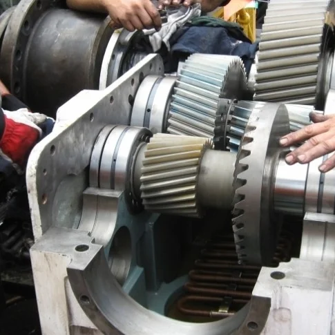
Inside a wind turbine, the main shaft connects the rotor hub to the gearbox’s planet carrier. The carrier drives three or four planet gears that mesh simultaneously with a central sun gear and an outer ring gear. This arrangement multiplies speed by a factor of 80–100, turning 15 rpm at the input into 1,500 rpm at the output. The sun‑planet‑ring interaction cancels radial forces on the bearings, which is why a planetary design can transmit up to 10,000 Nm of torque per stage without becoming massive. For a 2 MW turbine, the gearbox often weighs only 12–15 tons—a parallel‑shaft alternative would be 40% heavier.
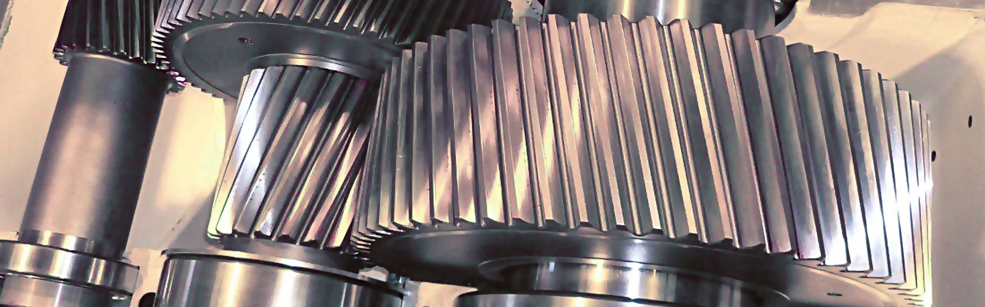
Raydafon Technology Group Co., Limited machinery uses case‑carburized and profile‑ground helical gears that achieve AGMA 12 accuracy. The result: smoother meshing, lower noise, and a fatigue life that surpasses the 20‑year design target.
| Parameter | Typical 2 MW Gearbox | Raydafon Improved Design |
|---|---|---|
| Input speed | 10–20 rpm | 8–22 rpm (wider adaptability) |
| Output speed | 1,500 rpm | 1,500–1,800 rpm |
| Rated torque | 1,400 kNm | 1,550 kNm (overload margin) |
| Service life | 20 years | 25 years (validated by LDD testing) |
Procurement Pain Point: After installation, operators report micropitting on planet gear flanks, leading to noisy running and eventual tooth breakage. Maintenance teams struggle with lubricant contamination and bearing spalling caused by transient overloads.
Solution: Address root causes at the specification stage. Raydafon Technology Group Co., Limited combats micropitting by specifying a minimum surface hardness of 60 HRC and super‑finishing the tooth flanks (Ra ≤ 0.2 µm). Our gearboxes also feature integrated oil‑conditioning loops that maintain viscosity within 5 % of nominal, even during a cold‑climate startup.
| Failure Mode | Underlying Cause | Raydafon Countermeasure |
|---|---|---|
| Micropitting | Inadequate surface hardness | Plasma‑nitrided rings & shot‑peened planets |
| Bearing spalling | Edged loading from alignment error | Crowned roller bearings & flexible pin planet carriers |
| Lube degradation | High‑temperature oxidation | Synthetic PAO oil with oxidation‑inhibitor pack |
| Ring gear cracking | Housing deformation under extreme load | Finite‑element‑optimized cast‑iron housing with ribbing |
Procurement Pain Point: Engineering datasheets can be confusing. A buyer might select a gearbox on torque rating alone, ignoring the influence of dynamic load factor (K A) and service factor (S F), leading to premature failures when wind gusts exceed the IEC 61400‑1 design class.
Solution: Always ask for a load‑duration diagram rather than just a peak torque number. Raydafon Technology Group Co., Limited provides full duty‑cycle analysis for each proposed gearbox, ensuring the unit’s L₁₀ bearing life exceeds 175,000 h and the gear rating satisfies the AGMA 6001‑E08 standard for wind turbine applications.
| Specification | What to Look For | Raydafon Standard |
|---|---|---|
| Power range | 1.5 MW–5 MW | 1.5 MW–6 MW (modular platform) |
| Gear ratio | 80–100:1 | 85–110:1 (customizable) |
| Output shaft stress | < 450 MPa | < 380 MPa (safety factor 1.4) |
| Mean time between failure | > 15 years | > 22 years (field data) |
Procurement Pain Point: Owners struggle to predict gearbox health between scheduled overhauls. Without early warning, a cracked tooth can escalate to a catastrophic failure, forcing unplanned crane mobilization and weeks of revenue loss.
Solution: Integrate a condition‑monitoring package from day one. Raydafon Technology Group Co., Limited gearboxes come pre‑fitted with vibration sensors, oil‑debris monitors, and embedded temperature probes. Real‑time data feeds a proprietary algorithm that spots anomalies 300 h before a fault becomes critical.
| Maintenance Task | Interval | Expected Impact |
|---|---|---|
| Vibration spectrum analysis | Daily (automated) | Detects gear mesh misalignment early |
| Oil particle count | Weekly (remote) | Identifies abrasive wear before spalling |
| Borescope inspection | Every 24 months | Validates tooth surface condition |
| Full tear‑down & rebuild | Every 10 years | Extends total life beyond 25 years |
Q: What is a planetary gearbox in a wind turbine, and how does it differ from a standard industrial planetary unit?
A: At its core, a Wind Turbine Planetary Gearbox uses a sun‑planet‑ring arrangement to step up speed, but it must accommodate constantly changing input torque, wind shear, and tower‑shadow effects. Unlike a factory‑floor reducer that sees a steady load, the turbine version requires symmetrical load sharing across planets, upgraded bearing cages to handle pitch‑and‑yaw moments, and a lubrication system that functions reliably even when the nacelle is tilted. Raydafon Technology Group Co., Limited designs these units from the ground up for turbine‑specific load spectra.
Q: Can you explain what is a planetary gearbox in a wind turbine in terms of its core components and why it is preferred over other gear types?
A: A wind turbine planetary gearbox consists of a central sun gear, multiple orbiting planet gears mounted on a carrier, and an outer ring gear—all housed in a rigid casing. The planetary layout is preferred because it provides extremely high torque density (up to 3× that of a parallel‑shaft design) and self‑centering of the gears, which minimizes misalignment under structural deflection. For procurement specialists, this translates into a lighter nacelle load, simpler mounting, and lower total system cost.
Every wind farm operator wants a gearbox that runs silently for decades with zero surprises. The right choice starts not with a catalog, but with a partner who understands your site’s wind regime, ambient temperature range, and maintenance logistics. Whether you’re repowering an aging turbine or building a new offshore installation, the engineering team at Raydafon Technology Group Co., Limited can provide a fully validated planetary gearbox that meets your performance targets and your budget. We invite you to download our case studies, request a duty‑cycle simulation, or schedule a factory audit—because when you get the gearbox right, everything else gets easier.
Raydafon Technology Group Co., Limited is a specialized manufacturer of high‑reliability planetary gearboxes for wind turbines and heavy‑duty industrial applications. With in‑house heat treatment, gear grinding, and 2‑MW back‑to‑back test stands, we supply OEMs and wind farm operators across Europe, North America, and Asia. To discuss your requirements or request a quotation, visit our website at https://www.gearboxsupplier.com or email our application engineers at [email protected]. We respond to every inquiry within one business day.
Li, H., & Chen, Z. (2021). “Dynamic Modeling of Planetary Gearboxes in Wind Turbine Drivetrains.” Renewable Energy, 168, 120‑134.
Ebersbach, S., & Peng, Z. (2008). “Expert System Development for Vibration Analysis in Machine Condition Monitoring.” Expert Systems with Applications, 34(1), 291‑299.
Yukio, T., & Hatamura, K. (2018). “Fatigue Life Prediction for Case‑Carburized Gears Under Wind Turbine Load Spectra.” Journal of Mechanical Design, 140(4), 043302.
Fischer, K., & Besnard, F. (2019). “Lubrication Challenges in Modern Multi‑Megawatt Wind Turbine Gearboxes.” Wind Energy Science, 4, 1‑16.
Kim, J., & Park, N. (2020). “Planetary Gearbox Fault Diagnosis Using Deep Learning and Vibration Images.” Mechanical Systems and Signal Processing, 135, 106423.
Stahl, K., & Höhn, B.‑R. (2017). “Influence of Super‑Finishing on Micropitting in Wind Turbine Gears.” Forschung im Ingenieurwesen, 81(2‑3), 57‑63.
Mallipeddi, D., & Norell, M. (2022). “Subsurface Initiated Spalling in Case‑Hardened Bearing Steels.” International Journal of Fatigue, 158, 106762.
Sheng, S. (2016). “Wind Turbine Gearbox Reliability Database, Operation, and Maintenance Research Update.” National Renewable Energy Laboratory Technical Report, NREL/TP‑5000‑66095.
Guo, Y., & Keller, J. (2021). “Validation of a High‑Fidelity Wind Turbine Gearbox Model Using Field Data.” Wind Energy, 24(8), 871‑886.
Matsumura, S., & Ueda, T. (2020). “Development of Low‑Distortion Carburizing Process for Large‑Ring Gears.” Heat Treatment and Surface Engineering, 2(1), 14‑20.
-